


With Natural Energy: TED-PG
Materialize themal expansion difference power generation


How it works
Incomplete thermal expansion makes power
Basis of Thermal Force
It may be Carring Coals to Newcastle to explain the basis of thermal force to the readers of this website. But let me get this straight first.
Imagine an one-dimensional carbon steel beam (see Fig. 1.1) whose ends are fixed while E, A and TEC are the elastic modulus, sectional area and average thermal expansion coefficient of the beam, respectively. The boundaries are set in ambient temperature and there is no axial force.
Next, raise the temperature of the beam by dT, which results in the thermal force of [E*TEC*dT*A]. The beam is about to expand, but the boundaries are fixed in the axial direction, so the beam keeps pushing the boundaries unless its temperature falls.
Assume that E, A, TEC and dT are 200GPa, 100mm2, 10E-6/deg-C and 100deg-C, respectively, and its resultant force is 20kN in compression. That is, a 1cm2-section steel bar can theoretically exert 20kN by raising its temperature by 100deg-C. Instead, when the temperature decreased by 100deg-C (see Fig. 1.1), the resultant force is the same 20kN in tension.
If something is inserted between the beam and its boundary (see Fig. 1.2), it is subject to such large compressive/tensional force, and if it's a device that directly or indirectly generates electric power, it works.
However, there are no such boundaries in actual. The base that the boundaries are fixed may expand/contract more or less due to the temperature change and/or such large thermal force, which results in the movement of the boundaries, releasing the thermal force.
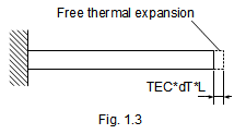
When the beam's length, L, is 1m, the free thermal expansion of the beam, i.e. the displacement that completely removes the force, is [TEC*dT*L] = 1mm (see Fig. 1.3). You can imagine how it is difficult to constrain such small displacement.
How to Constrain
So, here is an idea of "to constrain by another member". Assume two beam combination models that in each model both beams (Beams A and B, refer to Fig. 1.4) are completely connected each other at both ends, i.e. axial displacements are coupled each other. Next, set the following material for the two models. The E, A and L are set to be the same as the previous model.
Model 1 (M1): TEC of both beams are the same.
Model 2 (M2): TEC of Beams A and B are 15E-6 and 10E-6/deg-C, respectively.
Next, elevate temperature for each model in two load cases as shown below.
Load 1 (L1): Increase the temperature of both beams by 100deg-C.
Load 2 (L2): Increase the temperature of only Beam A by 100deg-C.
Then the thermal forces are distributed in both beams equally. The resultant thermal forces are summarized below for all combinations.
Case M1-L1: Zero (both beams expand equally)
Case M1-L2: 10kN [= 1/2*200E3*100*100*10E-6]
Case M2-L1: 5kN [= 1/2*200E3*100*100*(15E-6-10E-6)]
Case M2-L2: 15kN [= 1/2*200E3*100*(100*15E-6-0*10E-6)]
For all combinations, induced thermal forces are lower than that of the previous completely-fixed one-beam model (20kN). However, by changing the temperature and/or material of the two beams, we can generate fairly good thermal force, which I hope may results in practical power generation.
Find what's happened when the sectional rigidities are not the same between Beams A and B (see Fig. 1.5). Assume that the sectional area of Beam B is N times larger than that of Beam A in Case M1-L2 (Fig. 1.3). In the case, thermal force is calculated by [N/(N+1)*E*TEC*dT*A]. When N=4, the resultant thermal force is 16kN, which is 80% of that of the first ideal model (20kN).
It's important to think out how to maximize thermal force, i.e. the development of low/high thermal expansion material having high rigidity, member layouts, and where to increase/decrease temperature. There should be the best combination of these factors for each application.
Spring Support
Assume one steel beam whose one end completely fixed and another end supported by an axial spring, such as Fig. 2 in which the power generation device is an elastic body. Fig. 1.6 shows the relation between the thermal force F and the axial expansion when the beam's temperature is increased. The thin and bold arrows show the beam's internal force and the support's reaction force, respetively.
The expansion stops when both force are balanced with each other, i.e. it reaches x, and you can calculate the actual thermal force at the point. When both ends are supported by springs k1 and k2, replace k with 1/(1/k1+1/k2). Likewise, when one end is supported by another beam, replace k with the support beam's EA/L.
